The Anatomy of an Ice Plant
The core concept behind an ice arena refrigeration system is indirect cooling. The mechanical plant doesn't actually freeze the water directly. Instead, it chills a secondary coolant—typically a calcium chloride brine or a glycol solution—which is then pumped through miles of continuous piping embedded in the arena's concrete floor. As this freezing liquid travels under the floor, it absorbs heat from the water sprayed on top, causing that water to freeze.
This process relies on the primary refrigeration loop situated in the mechanical room. Heavy-duty compressors pressurize a primary refrigerant (like ammonia or Freon). The pressurized gas is condensed into a liquid, releasing massive amounts of heat (usually exhausted outside via a cooling tower). The liquid refrigerant is then allowed to expand rapidly inside a chiller barrel, dropping its temperature dramatically. The secondary coolant (brine or glycol) passes through this same barrel, exchanging its heat with the super-cooled refrigerant before being pumped back out to the rink floor.
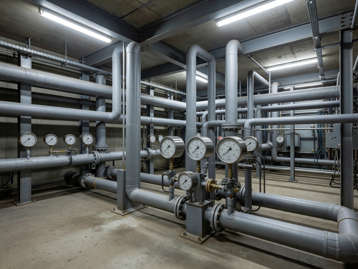
Monitoring and Preventive Servicing
Because an ice plant runs near-continuously, preventive mechanical servicing is the only way to avoid catastrophic failures. A breakdown in the refrigeration plant doesn't just mean a temporary pause in operations; if the plant is down for too long, the ice sheet will melt, destroying weeks of specialized surface preparation and forcing the facility to start over entirely.
Operators must meticulously monitor temperature differentials. The difference between the temperature of the coolant leaving the plant (supply) and returning to the plant (return) indicates how much heat is being absorbed from the arena. A widening differential may indicate that the floor is too warm, or it could point to a failing brine pump struggling to circulate the fluid fast enough.
Energy considerations are also paramount. Compressors draw enormous amounts of electricity. Efficient facilities use variable frequency drives (VFDs) on pumps and utilize waste-heat recovery systems—capturing the heat rejected by the compressors to melt snow in the Zamboni pit or pre-heat the building's domestic hot water.
Fault Detection and Warning Signs
Catching mechanical degradation early is key. Operators should conduct regular sensory checks of the plant room. Unusual vibrations in a compressor, the smell of ammonia, excessive oil consumption, or rapid frosting on pipes that are normally clear are all indicators that require immediate professional investigation.
What to Know: Condensation and Frost
While some frost on suction lines is normal in a refrigeration plant, sudden heavy ice buildup on compressors or valves can indicate a problem with the expansion valves or insufficient heat load. Conversely, sweating pipes in the arena space indicates poor humidity control, which will degrade the ice surface.
Mechanical Plant Checklist
- Record suction and discharge pressures of all active compressors daily.
- Verify the secondary coolant supply and return temperatures.
- Check compressor oil levels and look for signs of oil leaks on the mechanical room floor.
- Inspect the cooling tower for proper water flow and fan operation.
- Test emergency ventilation and hazardous gas detection sensors regularly.